 |
| Miniature Hydraulic Circuit |
This is the small hydraulic circuit that we use for demos. The entire thing is about the size of a sheet of paper. Although detached from the circuit in this picture, a small motor and pump contained in a manifold casing are attached to the two ports at the bottom right corner of the circuit. The small loop of metal wire (see top right corner of the circuit) is attached to the actuator and is used to attach a load to the actuator. Currently the system can lift a load of 300 pounds during actuation. Right now there's a minor problem with the reservoir not having a cap, making such tests very messy, but stay tuned for testing the circuit out to see if it can lift the other REUs at UMN!
 |
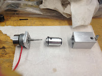
| From left to right: motor, pump, manifold |
Now for fun times with the pump! first I had to take apart the motor, manifold, and pump. In the complete circuit, the pump fits snugly into the manifold which prevents the external pump casing from rotating when the motor is running. I decided to take them all apart and see what everything looked like on the inside, including figuring out how the inlet and outlet in the pump connected to the manifold and the rest of the circuit. Then Jicheng (a grad student in my lab) and I decided to have a little fun and tried to see if we could actually watch the pump displacing fluid out of the outlet.
Some serious struggle-bus moments and a LOT of spilled oil later, we ended up with this. Enjoy!

No comments:
Post a Comment